Why thermal cycling testing matters
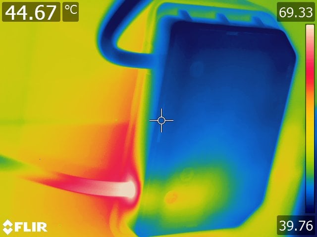
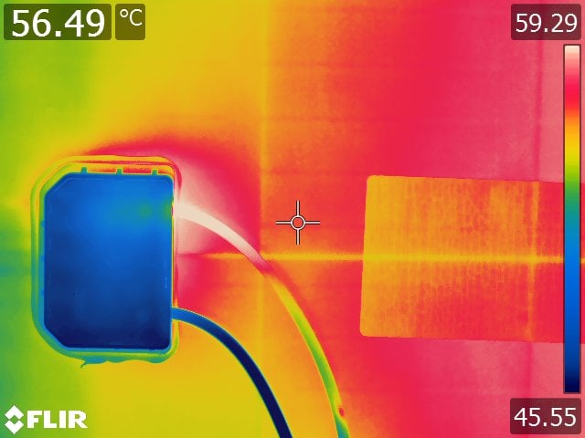
Following a year of site operation, Kiwa PI Berlin’s team in Spain were contracted to perform a routine inspection of a 12 MW Spanish site. During this inspection the Kiwa PI Berlin team discovered junction boxes with a noticeable temperature gradient via thermal imaging. Further investigations determined that 90% of the modules had junction boxes with this issue. The hottest part shown in these images was at the cable termination points inside the junction box.
The site owner spent more than 45,000€ over eight months to investigate the issue, inspecting every module on the site and conducting a root cause analysis. That analysis included Kiwa PI Berlin removing the junction box pottant on a sample of affected modules and discovering a crimping issue at the cable terminations. The bypass diode placement in the junction box prevented robust crimping of the cable, leading to weakened electrical connections. This issue can lead to higher electrical resistance and therefore lower performance, and in the worst case, to hot spots, arc faults and fires.
The module manufacturer was contacted but is not considering this a valid case for warranty replacement. The site owner will continue to evaluate the module performance and electrical insulation on an annual basis, and will attempt warranty claims in the future for any modules that experience catastrophic failures.
This type of issue can be missed in the TC200 thermal cycling test of IEC 61215 but has previously been identified during the extended TC600 thermal cycling testing in Kiwa PVEL’s PQP.
 |
 |
Materials assessed
These materials are susceptible to failure due to thermal stress and/or are critical for solder bond reliability:
|
 |
|
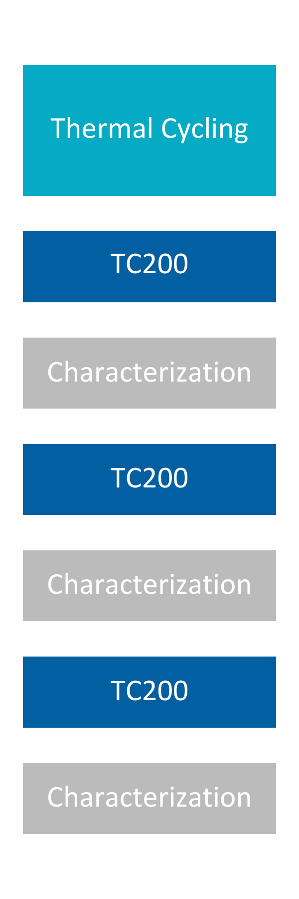
Modules are subjected to extreme temperature swings in an environmental chamber. They are first brought to a temperature of -40°C, after which the temperature increases to +85°C. While the temperature is increased, the modules are subjected to maximum power current providing additional field-relevant stress. The cycle repeats 600 times in total. Characterizations are conducted every 200 cycles. IEC 61215 testing requires 200 thermal cycles, which does not represent the expected operational lifetime of a PV module in most environments. With regard to solder bond fatigue, 25 thermal cycles equates to just one year of operation in Chennai, India, but it covers 50 years in Sioux Falls, South Dakota.* *Bosco, N.S., Silverman, T., Kurtz, S., “Climate Specific Thermomechanical Fatigue of Photovoltaic Module Solder Bonds,” Microelectronics Reliability, March 2016, DOI: 10.1016/j.microrel.2016.03.024 |
|